Beetleweight Combat Robot — Initial Design
Taking you through the design and build process of my 3lb combat robot! Even though it is only CAD, I plan on building it in the near future... 2021-03-09
How it All Started
As for many of my projects, I first got the inspiration for this robot by watching a YouTube video. The author, Robert Cowan, was simply talking about a antweight combat robot he made for a competition.
Antweight robots are some of the smallest types of combat robots, weighing a maximum of
1 lb. They are typically made of plastic and implement a fairly simple weapon system. The goal of the design is to reduce weight while maximizing destruction against other bots.
I used to think that combat robots were enourmous machines that cost thousands to manufacture, just like the ones on TV. However, this made me realize that competitions exist for robots of various sizes, from 1 lb all the way up to 220 lb. After watching a few hours worth of videos about the subject, I managed to piece together the first version of the design.
The First Design
The design goal of the first version of the robot was very simple: maximize mobility. Here is a 3D render of it:
I had previously identified that the lack of mobility of some bots caused them to loose matches. In order to combat this, the first version of my combat robot was reversible, meaning it could drive both right side up and up side down. Moreover, I decided to use omnidirectional wheels to make it as nimble as possible.
The Mecanum wheel is based on a tireless wheel, with a series of rubberized external rollers obliquely attached to the whole circumference of its rim. These rollers typically each have an axis of rotation at
45°to the wheel plane and at45°to the axle line. Each Mecanum wheel is an independent non-steering drive wheel with its own powertrain [...].
This first version looked very promising, but the design was flawed in many ways. First, it weighed 1.98 kg or 4.37 lb, meaningg it was way over the 3 lb weight limit imposed for beetleweights. Second, the weapon could only store 23.65 J of kinetic energy, which is completely useless for this weight class. Third, the 3D printed chassis of the robot was simply too weak to withstand any kind of hit from opponents. For those reasons, I knew a complete redesign would be necesary.
The Second Design
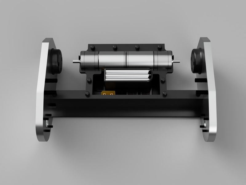
The design goals of this second version were completely different from the initial ones: use a simple and robust chassis to support a huge weapon. Here is that second version:

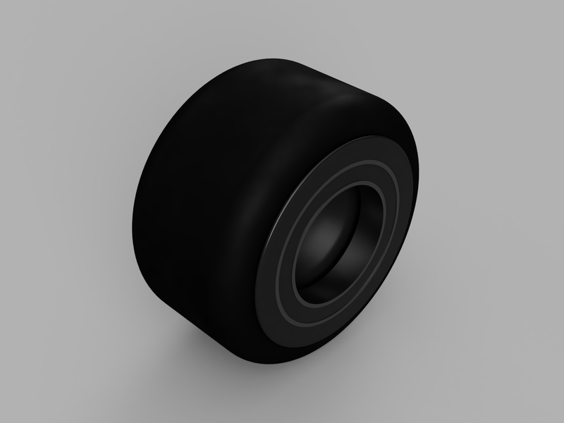
I started the design with 68 x 36 mm rubber tires, offering great traction. Then, I designed a completely custom wheel hub to accomodate said tires along with huge 30 x 42 x 7 ball bearings. Whereas most robots of this weight class use the motor shaft as a wheel axle, this assembly ensures that the wheel hubs are supported very effectively on both sides. Here is a 3D render of it:
After having designed the wheels, I immediately started prototyping the weapon. A few drafts and I landed on a design that is both robust and easy to manufacture. It consists of 24 steel bolts screwed into an aluminium tube, inside of which the motor bells press fit:
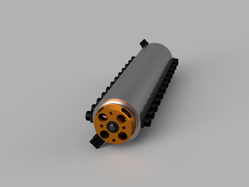
This design also improves the moment of inertia of the weapon, which is crucial for such a drum spinner.
The moment of inertia is a quantity that determines the torque needed for a desired angular acceleration about a rotational axis [...]. It depends on the body's mass distribution and the axis chosen, with larger moments requiring more torque to change the body's rate of rotation.
In essence, by concentrating the mass of the weapon on its outer perimeter, the energy it stores is greately increased when rotating at a predetermined angular velocity. In layman's terms, the weapon hits way harder. The current version stores a theoretical 238.45 J of kinetic energy and spins at an impressive 20 400 RPM.
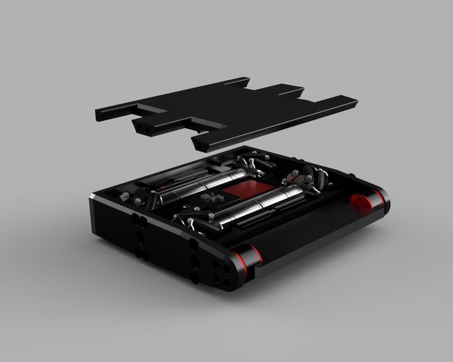
All of the required components were then encapsulated within a very robust chassis. It is made of an 8 mm thick aluminium exoskeleton with a symmetrical 3D printed body. It consists of two completely identical halves which are then assembled together using plastic pins, facilitating their replacement if one of them ever breaks. Here is a render of the whole body assembly containing all necessary electrical components:
Because of this robust chassis and its powerful weapon, I believe that this bot has a good chance of winning some matches! For anyone interested, here is a parts list for this version of the robot:
- Tattu R-Line 750mAh 3S LiPo
- Matek Systems PDB-XT60 W/ BEC 5V & 12V
- Flysky X6B 2.4G 6CH Receiver
- 10cm 18AWG XT60 Female Plug to XT30 Male Plug
- 20A X 2 Dual-Way Bidirectional Brushed ESC
- 60A Double Sides Brushless ESC
- 2x 12V 1000RPM Brushed Gear Motor
- 2x D3530 1700KV 3-4S Brushless Motor
- 2Pcs HS 18301 1/18 Scale Wheel
- 2x 2PCS 6806-2RS 30x42x7mm ball bearings
- 2x Bottom plate,
3D printed PLA - 2x Side plate,
Laser cut 6040 aluminium - 1x Accessories,
3D printed PLA 35 x 42 x 160 mm7075 aluminium pipe- 4x M3x4 Countersunk Screws
- 8x M3x12 Countersunk Screws
- 24x M5x6 Socket Head Screws
- 8x M5x16 Countersunk Screws
- 8x M5x20 Countersunk Screws
Updates Coming Soon!
When I get around to buying all the parts needed, totalling around
300 CAD, I will update this post for you to follow along!