Beetleweight Combat Robot
Building the Robot — Showcasing the entire build process of my beetleweight combat robot, including molding the polyeurethane wheels and machining the side plates and weapon. 2022-11-20
Introduction
After months of design and planning, it was finally time to build my combat robot. I divided this post into a few sections, representing the main parts of the building process. Since most of the design was done back when I had no experience with mills or lathes, I now realize that it is not optimal. Regardless, I hope you enjoy the read!
Initial Assembly
Generally, when I work on projects, I try my best to start with the highest risk steps; this way, if the project turns out to be more difficult than I initially anticipate, I can decide to put the project on hold without having spent large amounts of time and money on it.
For this project, however, I decided to start with one of the lower risk steps: the initial assembly. My reasonning was that I would be able to start by 3D prinding most of the metal parts using my 3D printer — the Ender 3 — to make sure everything fit together fine, after which I would be able to incrementally "upgrade" the robot with the required metal parts and polyeurethane wheels. This turned out to be a good decision.
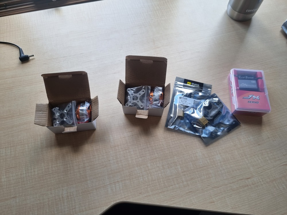
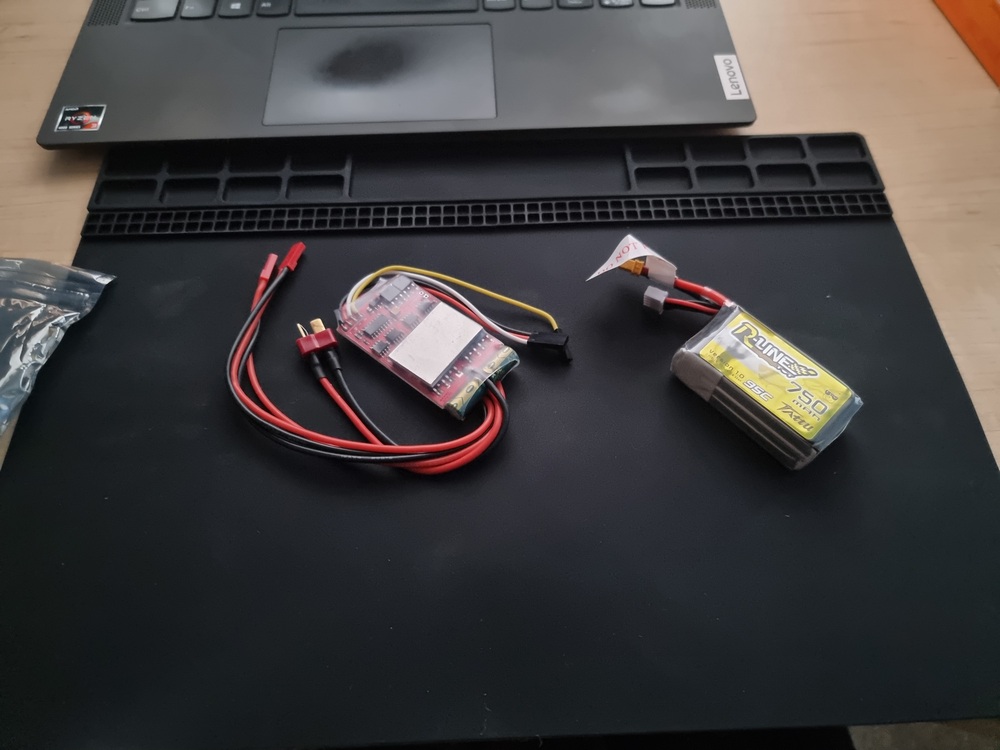
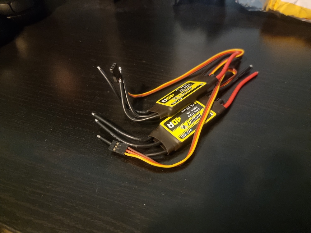
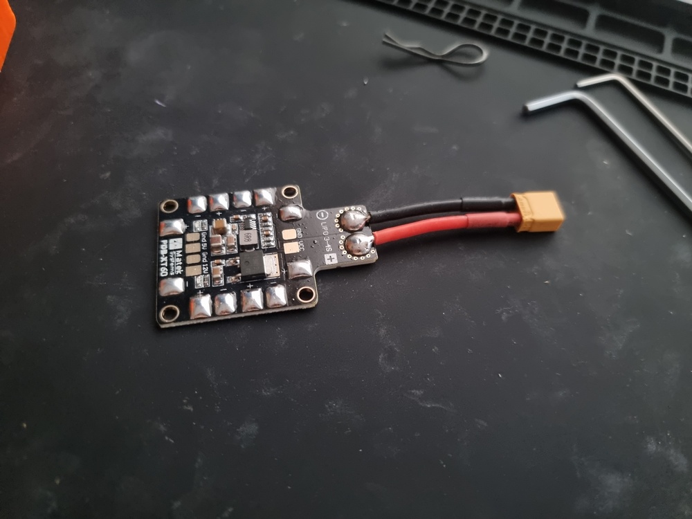
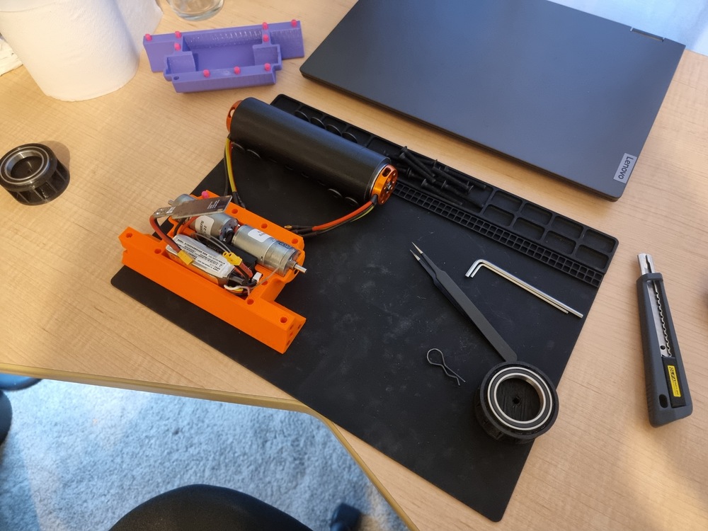
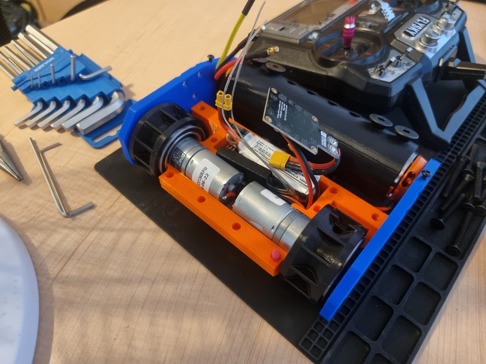
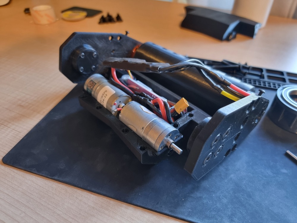
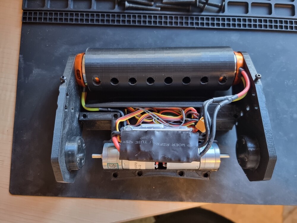
Once I had recieved the electronics I had ordered, I started building. I faced a few issues during this phase:
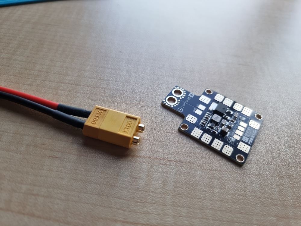
- It turned out that there was not enough room in the robot for the electronics I wanted to use. To fis this issue, I decided to remove the Power Distribution Board and replace it with a simple solder joint protected by heat shrink tubing.
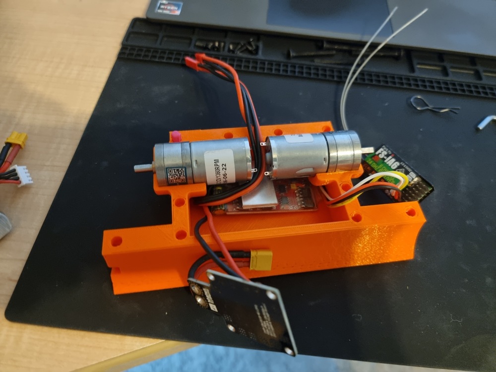
- The brushed drive motors did not have enough torque to move the robot precisely. To fix this issue, I started by attempting to soak the wheel ball bearings in isopropyl alcohol to remove the thitk lubricant they contained. This improved the situation somewhat. I then decided to order brushed motors with a higher gear reduction, which meand they would have more torque at the expense of reducing the top speed of the robot. In the end, the robot is plenty fast enough and is relatively controllable.
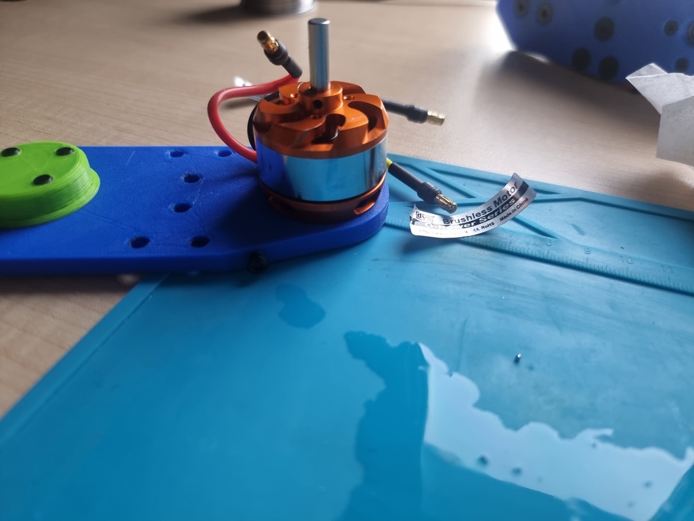
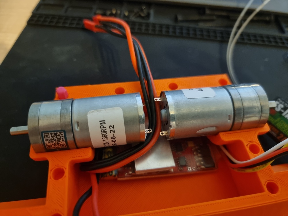
Here are some pictures of the initial assembly of the robot:
 |
 |
 |
 |
 |
 |
 |
 |
 |
 |
 |
 |
 |
|---|---|---|---|---|---|---|---|---|---|---|---|---|
Molding the Weels
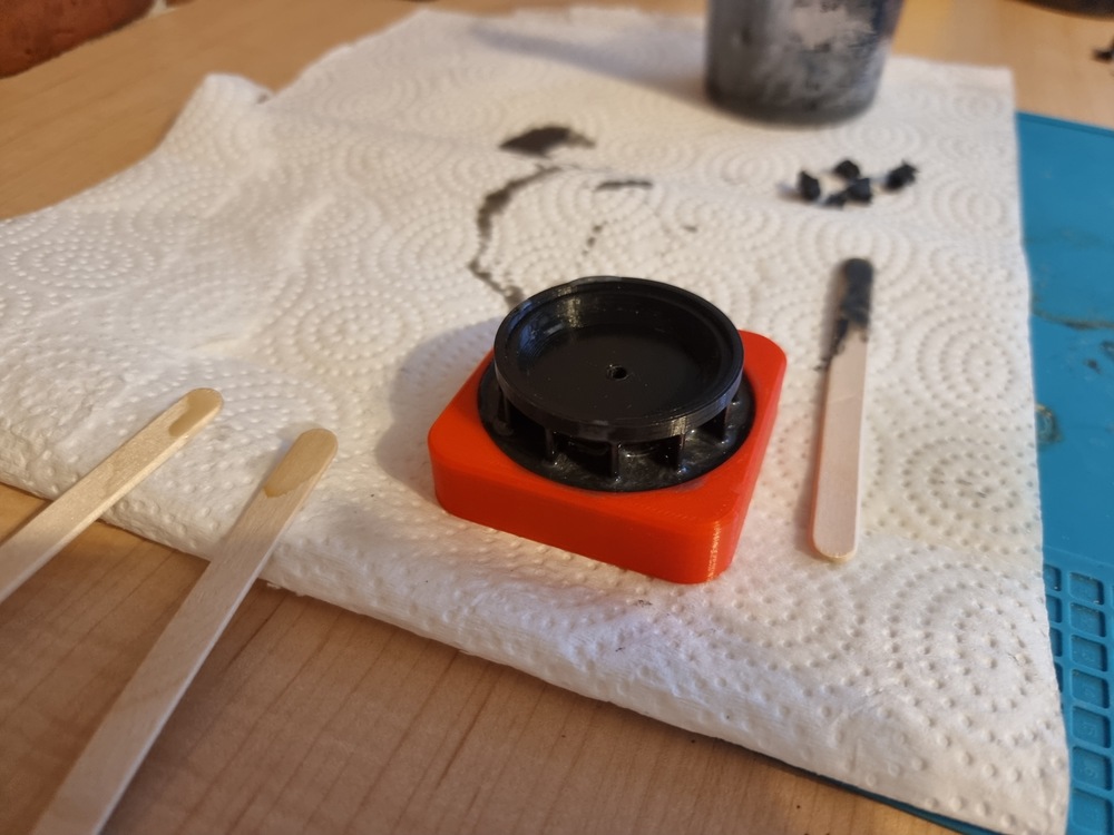
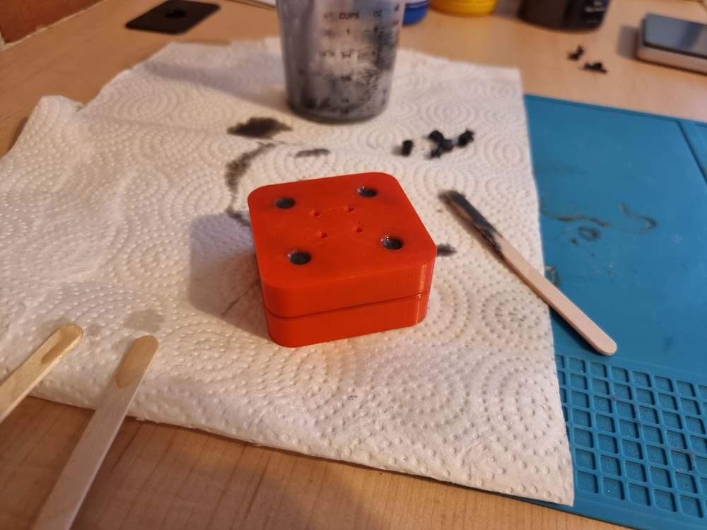
The next step in the build was molding the wheels using polyeurethane. I opted for Vytaflex 40 as it comes in two liquid parts that are mixed together to form solid rubber. It has a 40A hardness, which I believed was appropriate for my combat robot. I sourced a lot of the information on molding combat robot wheels from this video from Team Just 'Cuz Robotics and this video from Robert Cowan. The former recommended mica powder for pigmentation, which is what I ended up going with.
I designed a mold in Fusion 360 making sure to include the proper demolding features, and then 3D printed it using my Ender 3. Using the Vytaflex density from its datasheet and the 3D design volume Fusion 360 was reporting, I calculated that I would need a little less than 40g of polyeurethane to mold one wheel. I used 1/8 TSP of mica powder for each wheel, which turned out to work just fine. This was the first time I ever molded polyeurethane, and I ran into one main issue during this step of the build:
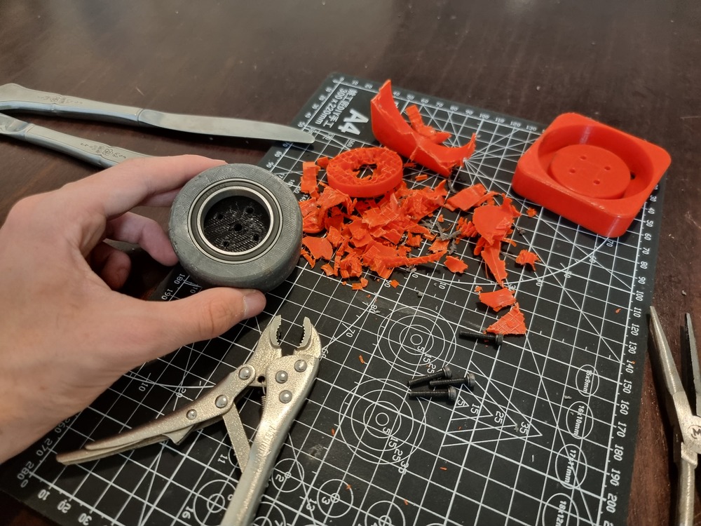
- I thought it would be viable to use some
WD-40as mold release, which ended up being wrong. For both wheels I had to destroy one half of the mold to remove the polyeurethane from it. Next time, I will make sure to use proper mold release, especially when using 3D-printed molds.
Here are some pictures of the molding process:
 |
 |
 |
 |
 |
 |
 |
|---|---|---|---|---|---|---|
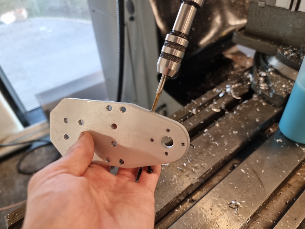
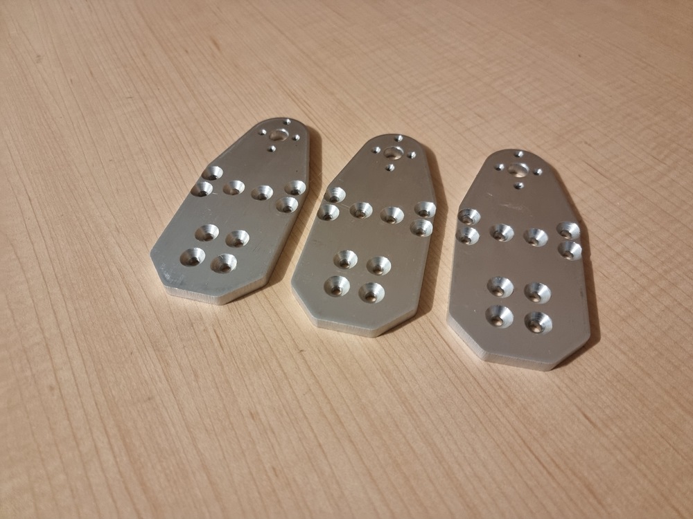
Machining the Side Plates
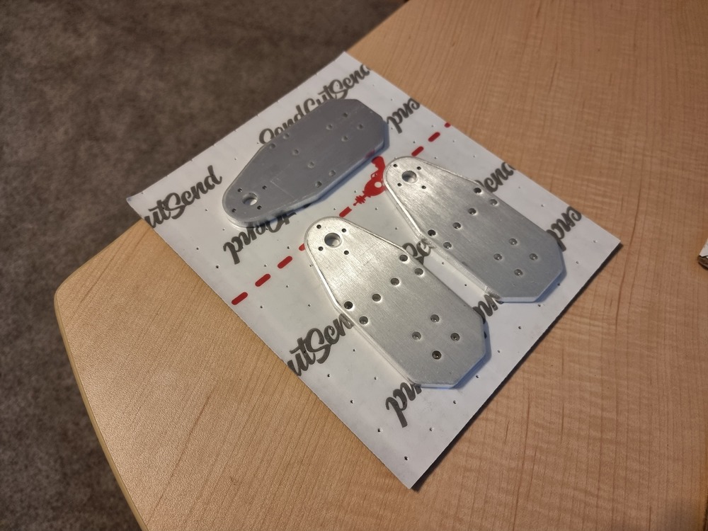
I then decided to continue the build by ordering the side plates from SendCutSend. I chose 1/4" thick 6061 aluminum for the side plates, as SendCutSend did not provide this specific thickness in 7075 aluminum. This makes the side plates more prone to bending during a fight, but I figured they were thick enough for that not to be much of an issue.
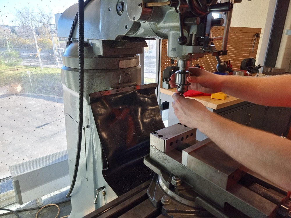
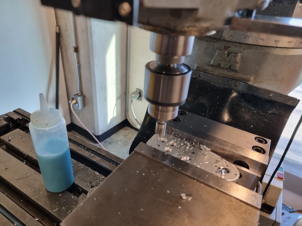
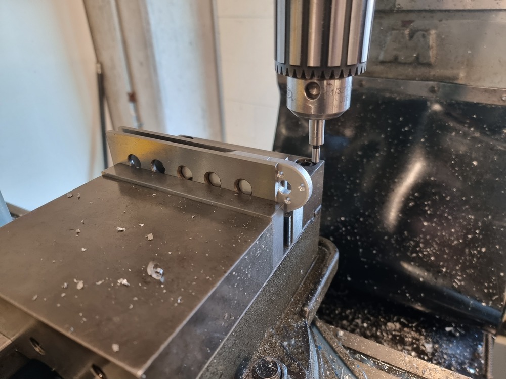
I needed to countersink the holes on the side plates of the robot, which meant I had finally reached the point at which I needed to learn how to use a mill to be able to continue with the build. Thankfully, uOttawa has a machine shop open to all students, the Brunsfield Centre. I signed up for the training offered by CEED, after which I was allowed in. Thanks to the amazing staff, I machined the side plates without running into any problems. That is, apart from breaking a tiny M3 tap in the part... it was bound to happen.
Here are some pictures of the machining process:
 |
 |
 |
 |
 |
 |
 |
 |
|---|---|---|---|---|---|---|---|
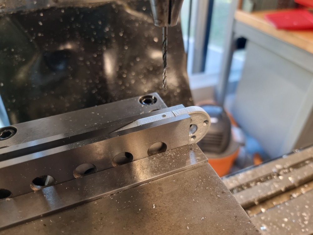
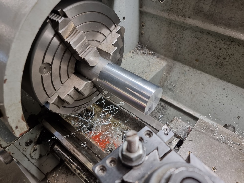
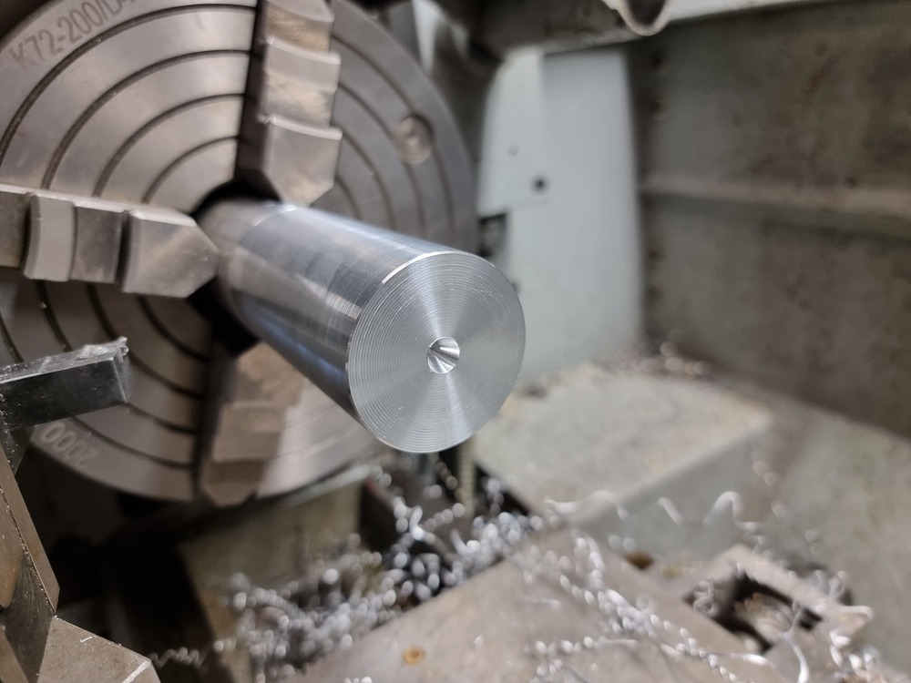
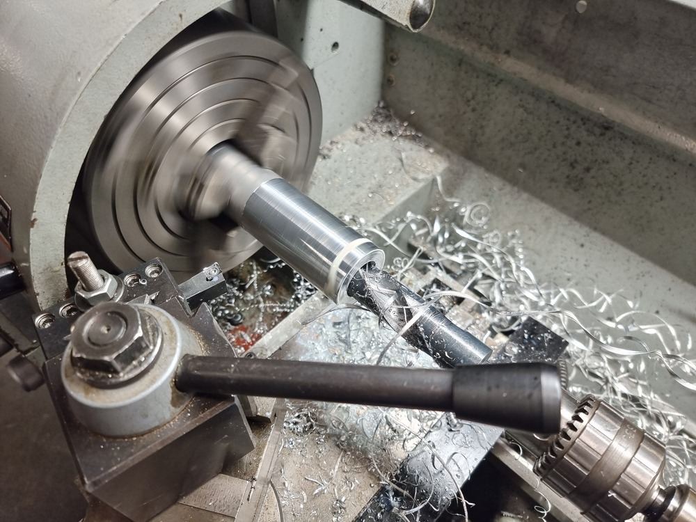
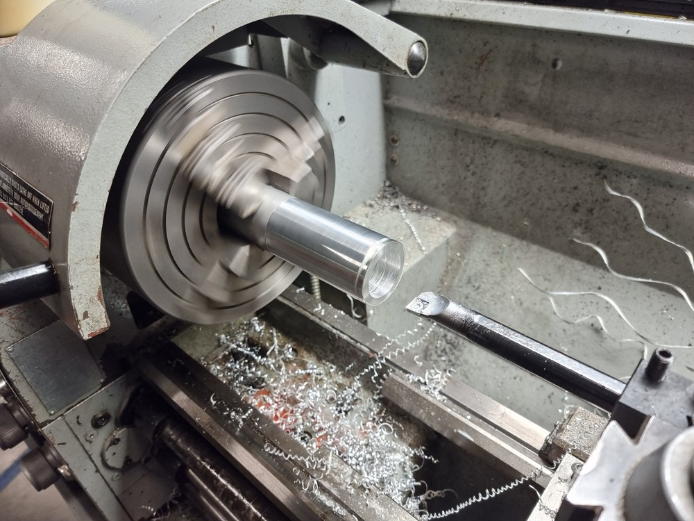
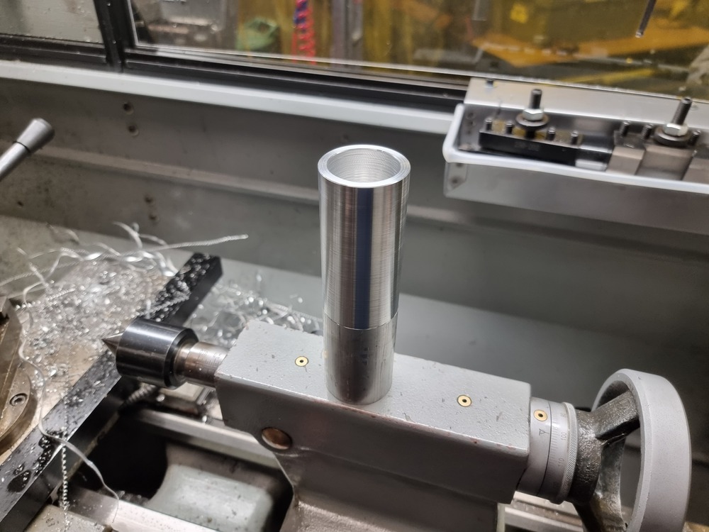
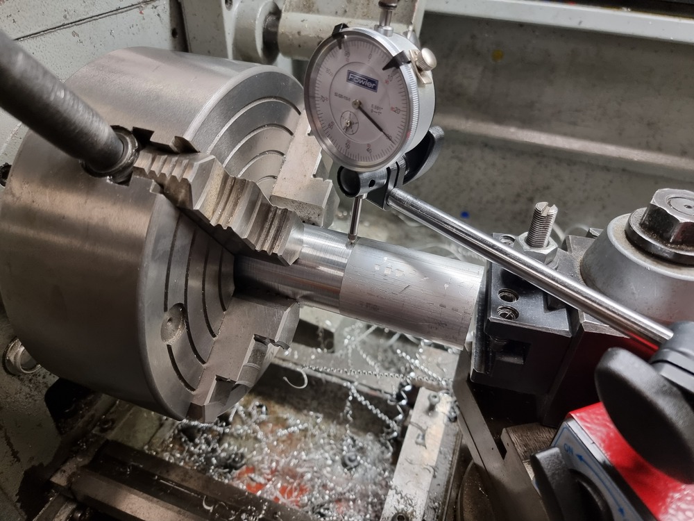
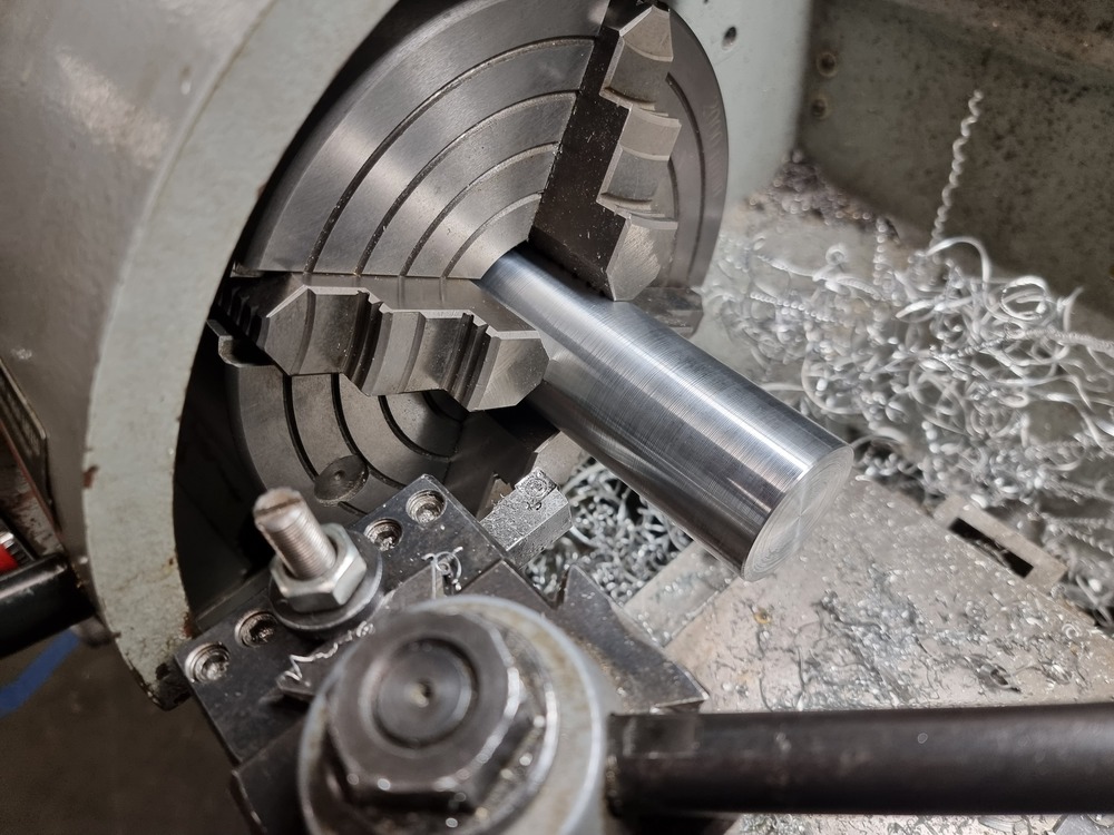
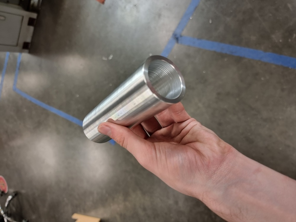
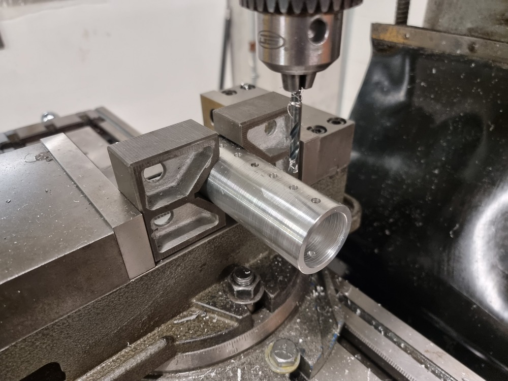
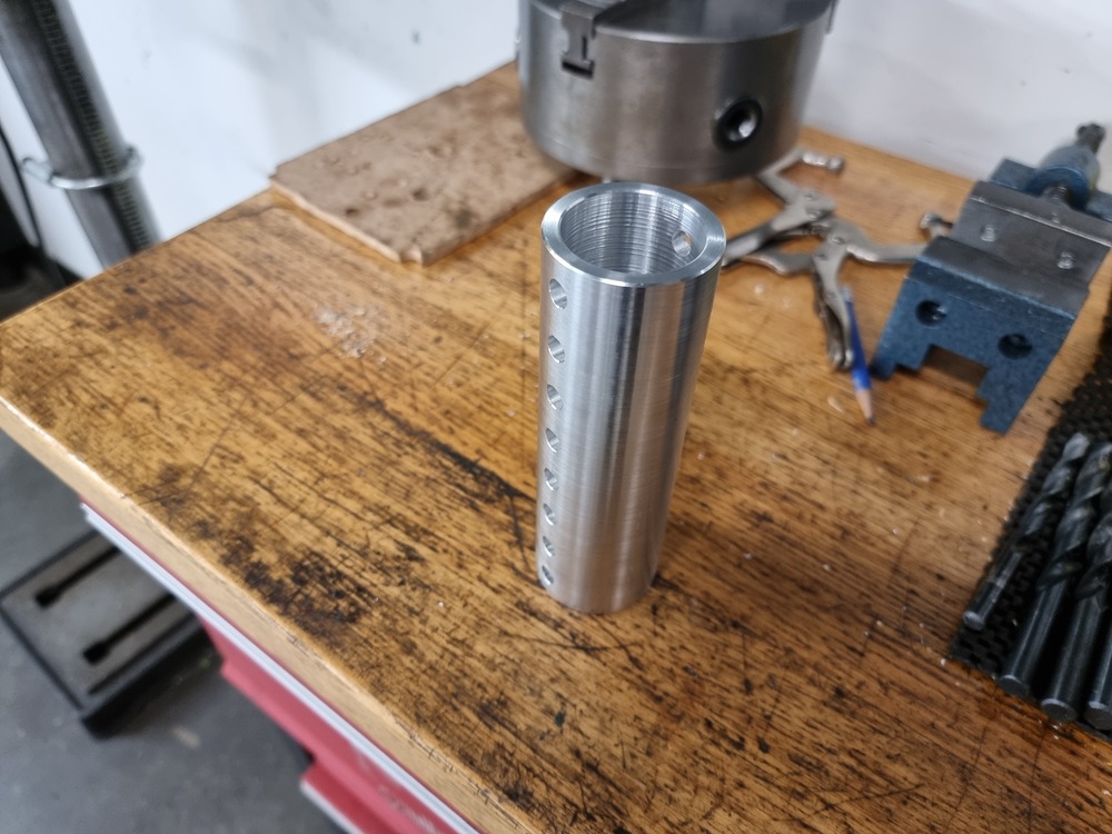
Machining the Weapon
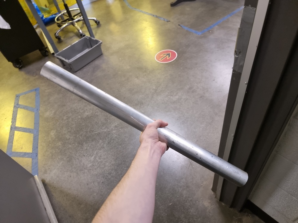
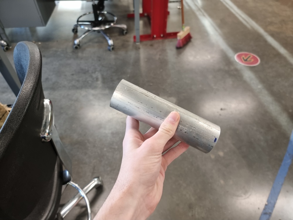
The final step was to machine the weapon. This was by far the riskiest part of the whole build because it consisted of a multitude of steps, and failing a single one meant starting the machining process again from scratch. I planned for potential complications by buying a 2 ft-long aluminum round bar stock, which would give me the leeway for screwing up around three times while still having enough material left for anether attempt. My confidence really was this low.
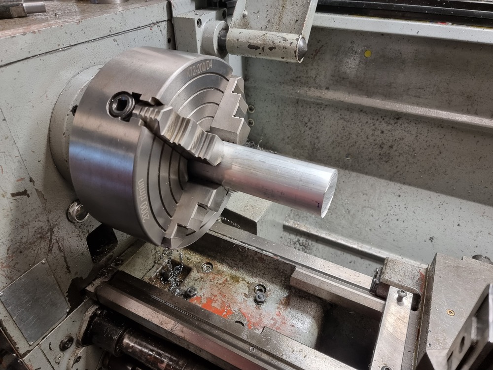
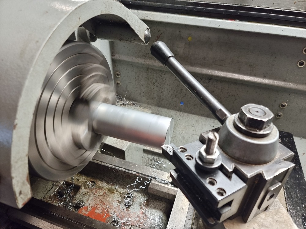
Thankfully, I did not have to start over from scratch and machined the weapon without any issues. I did not care about the surface finish of the weapon, so I figured I would machine half of it using a lathe, then flip it around in the chuck to machine the other. In the end, the jaws only left very minor marks on the weapon.
Here are some pictures of the machining process:
 |
 |
 |
 |
 |
 |
 |
 |
 |
 |
 |
 |
 |
 |
 |
 |
|---|---|---|---|---|---|---|---|---|---|---|---|---|---|---|---|
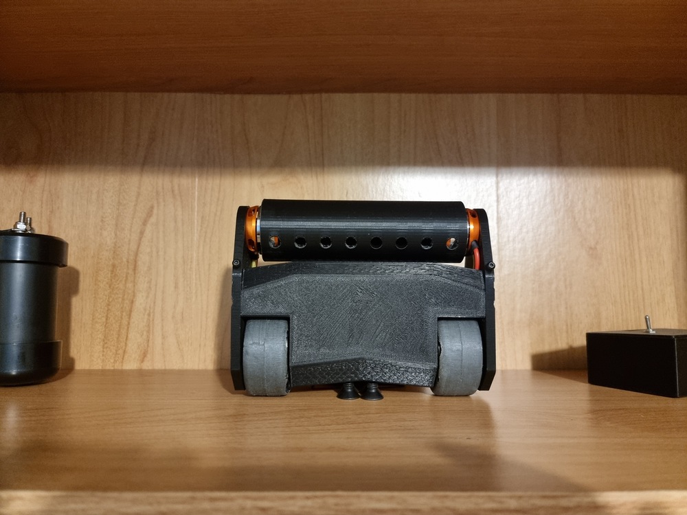
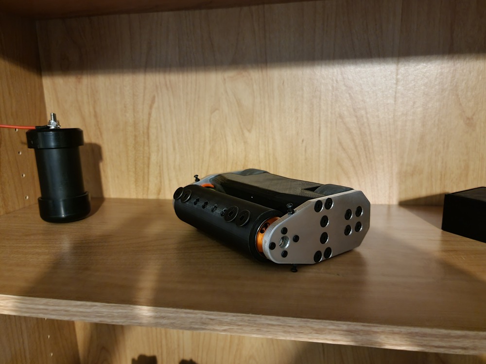
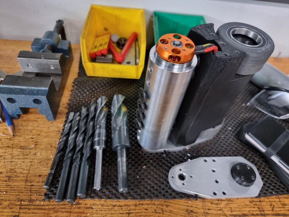
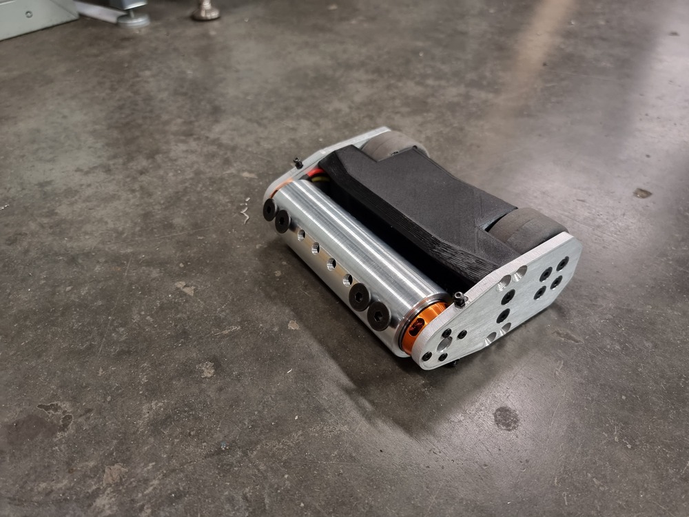
Final Design
With the build finished, I was able to test the combat robot fully for the first time. Below is a video of the robot hitting an older frame piece at around 35% power.
And, for anyone interested, here is the final parts list for the robot:
- Tattu R-Line 750mAh 3S LiPo
- Flysky FS-IA6 2.4G 6CH Receiver
- 20A X 2 Dual-Way Bidirectional Brushed ESC
- 2x HTIRC Hornet 40A 2-4S Two Way Brushless ESC
- 2x 12V 640RPM Brushed Gear Motor
- 2x D3530 1700KV 3-4S Brushless Motor
- 6PCS 6806-2RS 30x42x7mm ball bearings
- 2x Bottom plate, 3D printed PLA
- 2x Wheel Rim, 3D printed PLA
- 80g Vytaflex 40A Polyurethane Rubber
- 2x Side plate, laser cut 6061 aluminum
- 1x Accessories, 3D printed PLA
- 1.75" x 160 mm 6061 aluminum round bar stock
- 2x 10PCS M5x40 Countersunk Screws
- 2x 5PCS M8x10 Countersunk Screws
- 2x 10PCS M5x16 Countersunk Screws
- 1x 10PCS M3x10 Countersunk Screws
- 12x M3x10 Button Head Screws
- 4x M3 Nut
The final weight of the robot is 1288.8g, which is 72g under the 3lb weight limit. Including unused parts such as the leftover aluminum stock, the two extra bearings, the leftover Vytaflex and the four unused brushed motors, the total cost of the robot is 460.96 CAD. Note that this excludes all necessary tools, such as a mill and a lathe, a 3D printer, proper soldering equipment, molding supplies such as mixing cups and protective gloves, a LiPo charger, a transmitter, and so on.
Final Words
I learned a lot while working on this project, from how to use mills and lathes to how to tap threads and mold polyeurethane rubber. In the end, I am very happy with how the robot turned out. I hope you enjoyed reading about my experience building this robot, and I hope you learned something from it as well.